Turing Mesh Shader
The Turing architecture employs mesh shaders to create a new programmable geometric shading process. As threads are employed jointly to produce tiny meshes (meshlets) directly on the chip for consumption by the rasterizer, the new shaders introduce the compute programming approach to the graphics pipeline. The adaptability of the two-stage approach, which enables effective culling, level-of-detail techniques, as well as procedural generation, benefits applications and games dealing with high geometric complexity.
This post introduces the new pipeline and provides some specific GLSL rendering examples using OpenGL or Vulkan. The new features can be accessed by using DirectX 12 Ultimate extensions for OpenGL and Vulkan.
Motivation
The real world is a complicated, geometrically rich environment. Particularly outdoor scenes can contain tens of thousands of components (rocks, trees, small plants, etc.). Similar difficulties can be encountered when using CAD models for machinery with intricately curved surfaces and numerous small pieces. Large structures, like spaceships, are frequently detailed with "greebles" in visual effects. While very effective, the current graphics pipeline with vertex, tessellation, and geometry shaders, instancing, and multi draw indirect can still have limitations when the full resolution geometry reaches hundreds of millions of triangles and hundreds of thousands of objects. This is illustrated in Figure 1 by a number of examples.
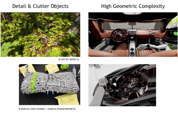
Other use-cases that weren't depicted above include procedural shapes or geometries from scientific computing (such as particles, glyphs, proxy objects, and point clouds) (electric engineering layouts, vfx particles, ribbons and trails, path rendering).
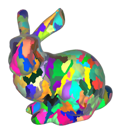
In this article, we'll examine mesh shaders for quick rendering of complex triangle meshes. As seen in figure 2, the initial mesh is divided into smaller meshlets. The vertex reuse within each meshlet should be optimised. With the additional hardware stages and this segmentation method, we can download less data overall while rendering more geometry in parallel.
Figure 2. Mesh shaders can break up large meshes into meshlets, which are then displayed.
 |  |
For instance, CAD data may contain tens of millions to hundreds of millions of triangles. There may still be a sizable number of triangles even after occlusion culling. In this case, several pipeline steps with fixed functions might do useless tasks and use excessive memory:
Even if the methodology doesn't change, the hardware's primitive distributor creates vertex batches by repeatedly scanning the indexbuffer. The hardware also performs vertex and attribute fetches for hidden data (backface, frustum, or sub-pixel culling)
The mesh shader offers new ways for developers to overcome these bottlenecks. In contrast to earlier methods, such as compute shader-based primitive culling , where index buffers of visible triangles are computed and indirectly rendered, the new approach enables the memory to be read only once and retained on-chip.
The mesh shader stage, which is similar to compute shaders, creates triangles for the rasterizer but inside uses a cooperative thread model rather than a single-thread programme model. The job shader is in the pipeline before the mesh shader. The job shader functions similarly to the tessellation's control stage in that it can generate work on-the-fly. Similar to the mesh shader, it uses a cooperative thread paradigm; however, its input and output are user defined rather than requiring a patch as input and tessellation choices as output.
Mesh Shading Pipeline
The traditional attribute fetch, vertex, tessellation, and geometry shader pipeline is supplemented with a new, two-stage pipeline. A task shader and mesh shader are part of the new pipeline:
- Task shader :a programmable device that works in groups and enables each to produce mesh shader workgroups (or not)
- Mesh shader : a programmable device that works in groups and enables each member to produce primitives
Using the internal cooperative thread paradigm discussed above, the mesh shader stage generates triangles for the rasterizer. In that it has the ability to dynamically generate work, the task shader functions similarly to the hull shader stage of tessellation. But the task shader also utilises a cooperative thread mode, just like the mesh shader. Instead of having to accept a patch as input and tessellation choices as output, its input and output are user defined.
The pixel/fragment shader interface is unaffected. Depending on the use-case, the old pipeline is still available and can deliver excellent results. The variations in pipeline styles are highlighted in Figure 4.
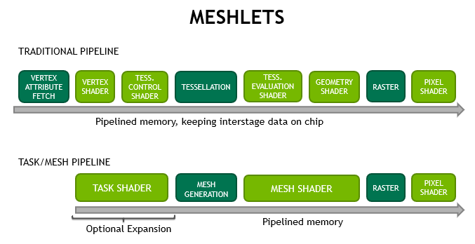
For developers, the new mesh shader pipeline offers a variety of advantages:
- Higher scalability through shader units by reducing fixed-function impact in primitive processing. Modern GPUs' ability to be used in a wide range of applications allows them to add more cores and enhance the performance of their shaders' generic memory and arithmetic operations.
- Bandwidth-reduction, as de-duplication of vertices (vertex re-use) can be done upfront, and reused over many frames. The hardware must constantly search the index buffers due to the existing API model. Greater vertex reuse results from larger meshlets, which also reduces bandwidth needs. Additionally, programmers are free to create their own compression or procedural creation techniques. You can completely avoid getting more data by using the optional expansion/filtering via task shaders. task shaders allows to skip fetching more data entirely.
- Flexibility in defining the mesh topology and creating graphics work. Previous tessellation shaders had a fixed set of tessellation patterns, and geometry shaders had an unattractive programming style with inefficient threading that produced triangular strips per-thread.
Mesh shading adheres to the compute shader programming style, enabling developers the option to employ threads for various tasks and transfer data across them. The two stages can also be utilised to perform general compute tasks with one level of expansion when rasterization is deactivated.
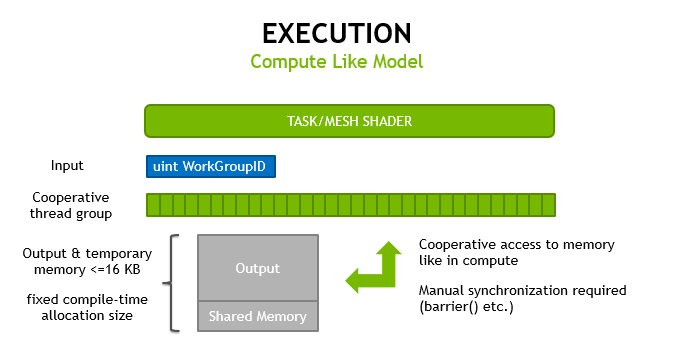
Mesh and task shaders both use cooperative thread groups to compute their outputs and only accept a workgroup index as an input, using the same programming approach as compute shaders. These run on the graphics pipeline, so memory moved between stages and stored on-chip is managed directly by the hardware.
As the threads may later access all vertices within a workgroup, we'll demonstrate how this can be leveraged to do primitive culling. Figure 6 demonstrates how task shaders can handle early culling.
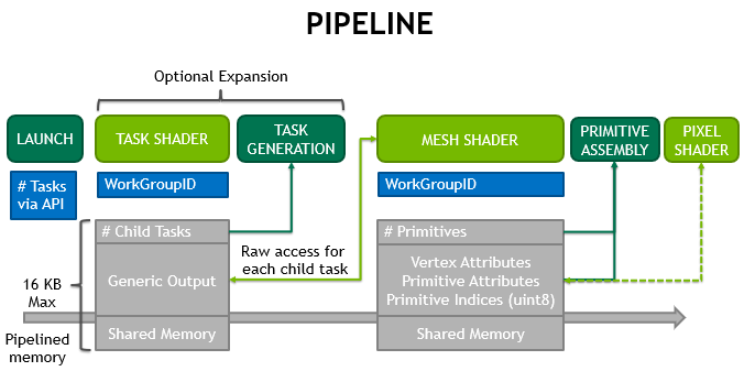
A set of primitives can be culled early or LOD selections can be made in advance thanks to the optional expansion via task shaders. For small meshes, the method replaces multi draw indirect or instancing because it scales across the GPU. This setup is comparable to the tessellation control shader controlling how much a patch (or task workgroup) is tessellated before impacting how many tessellation evaluation invocations (or mesh workgroups) are generated.
A single task workgroup can only emit so many mesh workgroups. A task can create up to 64K children on hardware from the first generation. The total number of mesh children across all tasks inside the same draw request is unbounded. Likewise, if no task shader is employed, no limits exist on the amount of mesh workgroups generated by the draw call. Figure 7 illustrates how this works.
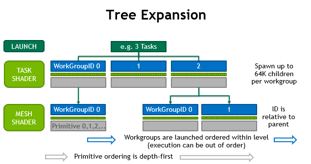
There is a guarantee that children of task T will launch after those of task T-1. Task and mesh workgroups, however, are fully pipelined, thus there is no need to wait for the completion of earlier offspring or tasks.
When creating or filtering dynamic work, the task shader should be used. Utilizing only mesh shaders is advantageous for static setups.
The meshes and the primitives contained within them maintain the order created by the rasterization process. Basic compute-trees can be implemented using task and mesh shaders when rasterization is disabled.
Pre-Computed Meshlets
As an illustration, we render content that is static and whose index buffers don't change frequently. So, when uploading vertices/indices to device memory, the expense of creating the meshlet data can be concealed. When the vertex data is likewise static (no per-vertex motion, no changes in vertex positions), additional advantages can be realised, enabling the precomputing of data needed for quickly culling whole meshlets.
Conclusion
The following are some important conclusions:
- By doing a single index buffer search, a triangle mesh can be divided into meshlets. Vertex cache optimizers, which aid in traditional rendering, also enhance meshlet packing effectiveness. Improved early rejection is made possible by more complex clustering at the task shader stage (tighter bounding boxes, coherent triangle normals etc.).
- Prior to the hardware needing to allocate vertex/primitive memory for an on-chip mesh shader invocation, the task shader enables skipping a group of primitives. Additionally, if needed, it allows for the generation of several child invocations.
Comments
Post a Comment